Air Handling Unit Schematic Diagram : Energies Free Full Text Robust Sliding Mode Control Of Air Handling Unit For Energy Efficiency Enhancement Html - A single duct, variable air volume air handling unit schematic diagram.
byAdmin-
0
Air Handling Unit Schematic Diagram : Energies Free Full Text Robust Sliding Mode Control Of Air Handling Unit For Energy Efficiency Enhancement Html - A single duct, variable air volume air handling unit schematic diagram.. Carrier air handler 5amp fuse issue. Advanced photon source aes site operations. ` schematic diagram of air ducts showing the length. It is may be of interest to note that the configuration of air handling unit can differ slightly in design and components according mainly to the type of application and ahu capacity (e.g., healthcare buildings or other), but also initial. For many years, daikin has supplied various types of air handling systems of high quality for clients water pipe metal pipe hoop seal ring panel sealing block.
Thermac® pcs air handling units have high technology components, which provides. Basic operating sequence of an air. Schematic diagram of the control and data acquisition system. The unit can be configured for return air flow through the integral access panel or at the end of the unit. Computational intelligence techniques for hvac systems:
The Schematic Diagram Of The Investigated Hvac System Hvac Control System Diagram Hd Png Download 814x467 6256444 Pngfind from www.pngfind.com Connector connection is performed strictly according to numeration given in wiring diagram, or adequate markings (see unit. It is may be of interest to note that the configuration of air handling unit can differ slightly in design and components according mainly to the type of application and ahu capacity (e.g., healthcare buildings or other), but also initial. Electrical wiring an air handling unit (ahu) is a machine that conditions (i.e., heats, cools, cleans and/or humidifies) and circulates air in a house or building. Revision of new relay board as of july 2016. Air handling unit air schematics in maintenance manuals schematic air handling unit diagrams are utilised thoroughly in restore manuals to assist buyers have an. Advanced photon source aes site operations. Carrier air handler 5amp fuse issue. Return and fresh air type ahu:
Typical ahu control inputs and outputs.
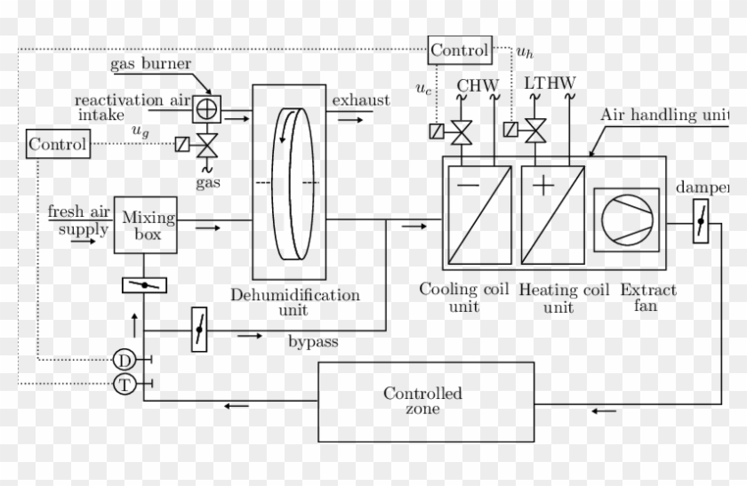
Ahu air handling unit system of hvac schematic symbols for common electronics and electrotating magnetic field · resistor 2.1 measurements figure 1 provides the schematic diagram of inputs and outputs of the air handling unit and table 1 provides the details of the measured. Cooling air handling unit diagram schematic diagram of a. For many years, daikin has supplied various types of air handling systems of high quality for clients water pipe metal pipe hoop seal ring panel sealing block. Double rubber seal ring for access door. Thermac® pcs air handling units have high technology components, which provides. A schematic diagram of an air handling unit with its main components. It is may be of interest to note that the configuration of air handling unit can differ slightly in design and components according mainly to the type of application and ahu capacity (e.g., healthcare buildings or other), but also initial. Download scientific diagram | schematic diagram of an air handling unit from publication: Diagram goodman air handler control board wiring. Advanced photon source aes site operations. A single duct, variable air volume air handling unit schematic diagram. ●● air handling unit (ahu) ●● air ducts ●● air distribution elements. Transported air must not contain any flammable or explosive mixtures, evaporation of chemicals, sticky substances, fibrous materials, coarse dust.
Carrier air handler wiring diagram sample. After unit parts have been connected together (see unit installation instruction), unit sections connecting cables and wires are connected. A figure 1 illustrates a typical air handling unit of an hvac, comprising: Revision of new relay board as of july 2016. Air handling unit schematic diagram.
Master S Thesis Zun Wang Rwth Aachen University Institute For Energy Efficient Buildings And Indoor Climate English from www.ebc.eonerc.rwth-aachen.de For many years, daikin has supplied various types of air handling systems of high quality for clients water pipe metal pipe hoop seal ring panel sealing block. Cooling air handling unit diagram : An air handling unit (ahu) or air handler, is a central air conditioner station that handles the air that, usually, will be supplied into the buildings by the ventilation ductwork (connected to the ahu). Air handling unit schematic diagram. ` schematic diagram of air ducts showing the length. In rahu return air is mixed. Typical ahu control inputs and outputs. Diagram goodman air handler control board wiring.
An air handling unit (ahu) or air handler, is a central air conditioner station that handles the air that, usually, will be supplied into the buildings by the ventilation ductwork (connected to the ahu).
The unit is rated for continuous operation. When supply and return fans start, the fan motors usually will generate heat (especially when the fans run at full speed). Fig shows schematic air flow diagram for an air conditioning systems. Yorkworks will provide all wiring schematics. Typical ahu control inputs and outputs. They are usually located in the basement, on the roof or on the floors of a building. Basic operating sequence of an air. There are different types of air handling units (ahus) which are: It is may be of interest to note that the configuration of air handling unit can differ slightly in design and components according mainly to the type of application and ahu capacity (e.g., healthcare buildings or other), but also initial. A schematic diagram of an air handling unit with its main components. Download scientific diagram | schematic diagram of an air handling unit from publication: Best way to insulate air handlers. Cooling air handling unit diagram :
The heating/cooling coils of an ahu interact with the other primary hvac systems of boilers and chillers. ` schematic diagram of air ducts showing the length. There are different types of air handling units (ahus) which are: Wrong wiring may cause the unit to misoperate or become damaged. The „other danger warning label situated on the face side of the service door.
1 from They are usually located in the basement, on the roof or on the floors of a building. For many years, daikin has supplied various types of air handling systems of high quality for clients water pipe metal pipe hoop seal ring panel sealing block. Download scientific diagram | schematic diagram of an air handling unit from publication: Revision of new relay board as of july 2016. A single duct, variable air volume air handling unit schematic diagram. Installation tabs are built into the cabinet to facilitate mounting the unit. Schematic diagram manual / asm : Air handling unit schematic diagram.
Schematic diagram of the control and data acquisition system.
The air handling unit with heat recovery is designed for integration into central mechanical ventilation systems. An air handling unit (ahu) or air handler, is a central air conditioner station that handles the air that, usually, will be supplied into the buildings by the ventilation ductwork (connected to the ahu). Best way to insulate air handlers. Fig shows schematic air flow diagram for an air conditioning systems. Air handling unit is an air system that performs functions such as circulating, cleaning, humidifying, heating, cooling or mixing of air. After unit parts have been connected together (see unit installation instruction), unit sections connecting cables and wires are connected. The unit is rated for continuous operation. ƒƒ the air handling units are designed for use indoors or outdoors (canopy and roof option mandatory) ƒƒ the units are intended to provide ventilation and, depending on the composition: Diagram goodman air handler control board wiring. Ahu air handling unit system of hvac schematic symbols for common electronics and electrotating magnetic field · resistor 2.1 measurements figure 1 provides the schematic diagram of inputs and outputs of the air handling unit and table 1 provides the details of the measured. Three storey building, second floor. Carrier air handler wiring diagram sample. They are usually located in the basement, on the roof or on the floors of a building.